Harness Builder - Schematic
Harness Builder - Layout
Component Creator
Cable Creator
Getting Started
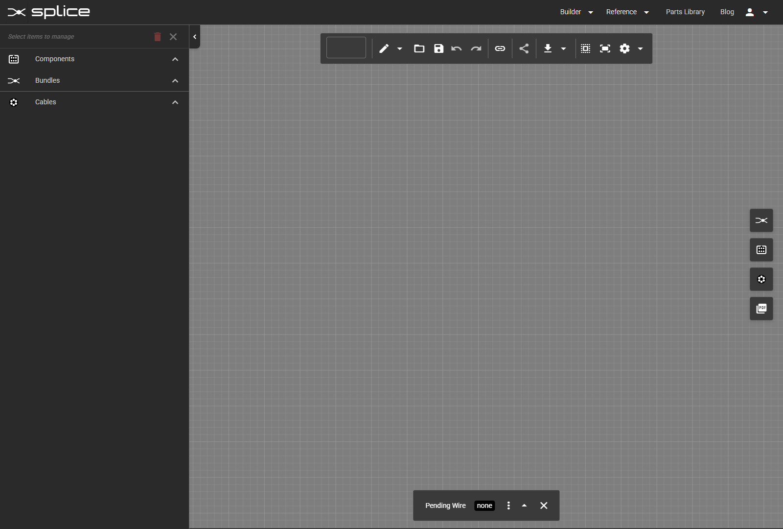
Open the Harness Builder
To begin, click Builder → Harness Builder in the top navigation menu. This opens the interactive canvas where you will create your cable harness or assembly schematic.
- The left sidebar displays your harness summary and bill of materials (BOM).
- The center canvas is where you place components and make connections.
- The right toolbar provides access to the Component Library, Wire Library, Cable Library, and PDF Page Configuration.
- The top toolbar contains tools for saving, editing project details, exporting designs, and advanced features.
- The bottom toolbar shows wire properties, swap status, or other context-specific details.
Settings & Preferences
Configure Your Workspace
Access Settings from the top toolbar or context menu to customize your design environment.
Grid Settings
- Toggle grid visibility for alignment reference.
- Adjust grid spacing to suit your layout.
- Enable snap-to-grid for precise placement.
Unit Preferences
- Select wire diameter units: AWG or mm².
- Select length units: Imperial (inches) or Metric (mm).
- Units update automatically throughout the BOM and exports.
Harness Builder Interface
Toolbar & Controls
Familiarize yourself with the main toolbar and interface elements.
Main Toolbar
- New: Start a new blank harness.
- Edit: Project name, description, and notes.
- Open: Open existing harness assemblies.
- Save: Save your harness. Red indicator shows unsaved changes.
- Save As: Save a copy with a new name.
- Undo/Redo: Command history with hover previews.
- Bulk Connect: Connect multiple pins quickly.
- Share: Share a harness via public link.
- Labels: Toggle visibility of labels, pin names, wire info.
- Export: PDF, SVG, PNG, and WireViz formats.
- Box Select: Select multiple items.
- Fit to View: Fit the design to the screen.
- View Mode: Toggle between schematic and layout views.
- Settings: Grid, snap, and display preferences.

Adding Components
Search and Select Components
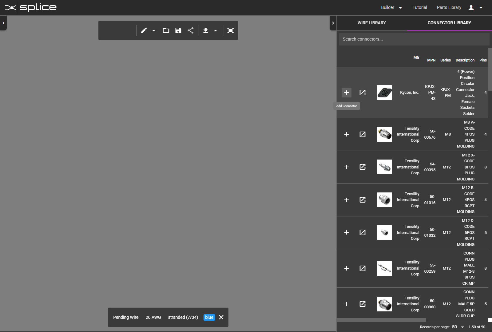
Click the Component Library button on the right toolbar to open the search window. You can browse by category or shape, search by part number, or filter by specifications.
- Browse by category: Circuit Breakers, Fuses, Connectors, Switches, etc.
- Browse by shape: Circular, USB, D-Sub, Rectangular, Ferrule, Quick Disconnect, Ring Terminal, Terminal Block.
- Search by part number, manufacturer, or keyword.
- Filter results by pin count, voltage rating, or series.
- Click to add the selected component to your harness.
- Click to open the datasheet.
Component Categories & Shapes
 Circular: Round multi-pin connectors
- USB: Universal Serial Bus connectors
 D-Sub: D-subminiature connectors
 Rectangular: Rectangular connectors
 Ferrule: Wire-end sleeve terminals
 Quick Disconnect: Spade and blade terminals
 Ring Terminal: Ring and lug terminals
 Terminal Block: Barrier strip connectors
 Circuit Breakers: Overcurrent protection
 Fuses: One-time overcurrent protection
- Push Buttons: Momentary and latching controls
 Switches: Manual control elements
 Relays: Electromechanical switching
- Contactors: Heavy-duty power switching
- Timers: Time-delay control relays
- Power Supplies: Voltage conversion modules
 Motors: Electric motor components
- Fans: Cooling and ventilation
- PCBs: Printed circuit boards
 Resistors: Fixed and variable resistors
 Capacitors: Energy storage components
 Diodes: Rectifiers and semiconductor switches
 Inductors: Coils and chokes
 Transformers: Voltage transformers
 Inverters: DC-to-AC conversion
- Splices: Wire joining and connections
- Batteries: Power cells and packs
 Solar Cells: Photovoltaic modules
- Other: Miscellaneous components

Creating Generic Components
Build Custom Components
When a component isn't available in the library, you can create a generic component with custom pin counts, shapes, and properties.
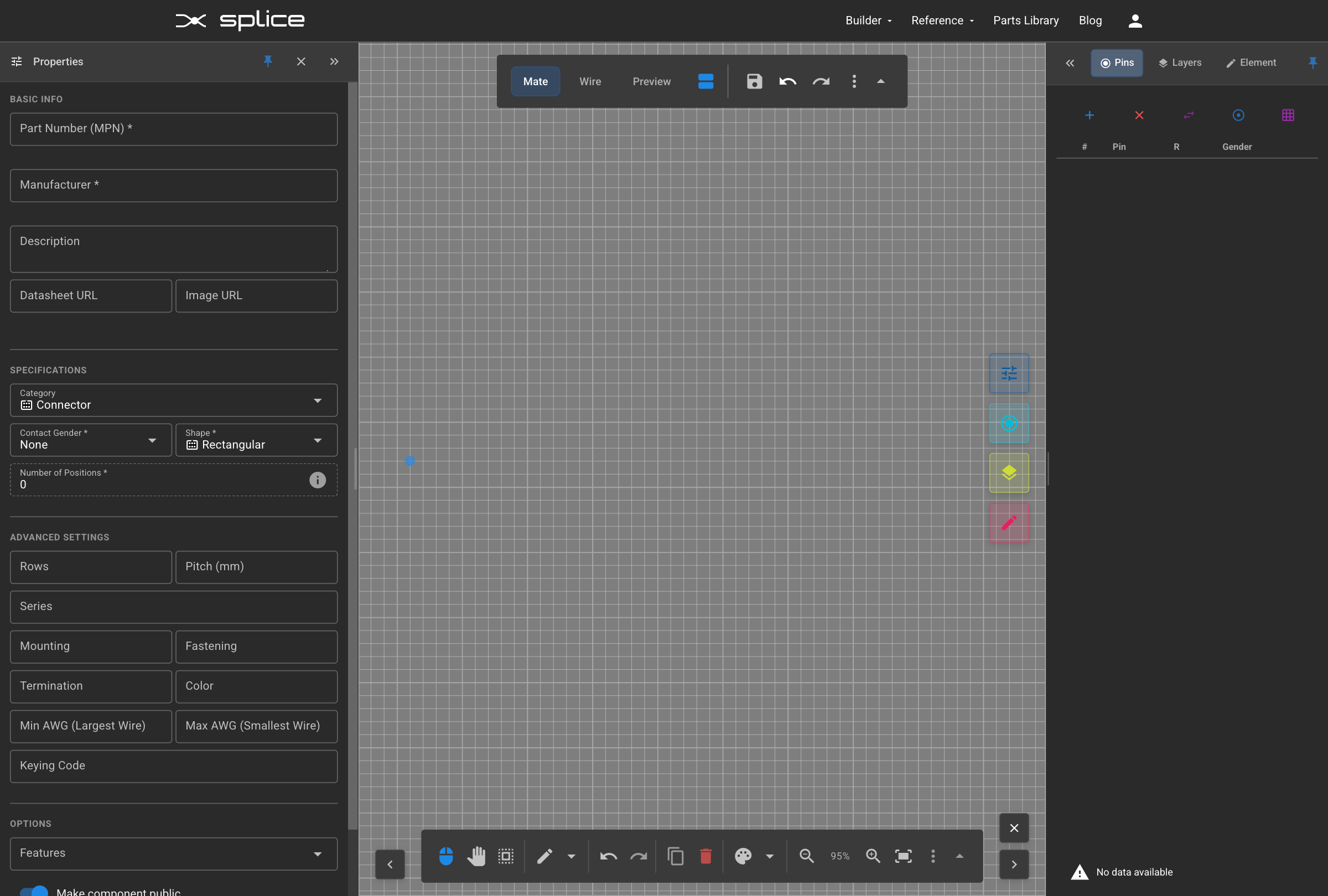
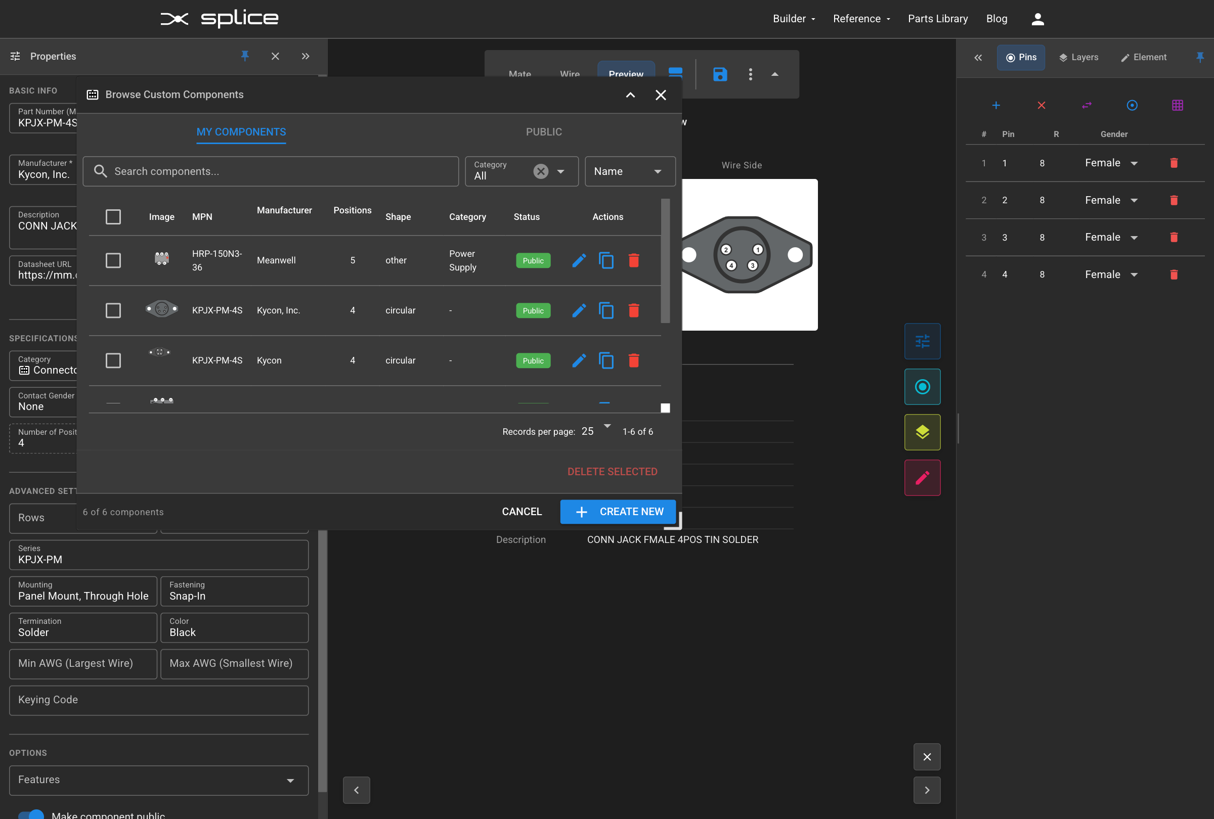
Creating a Generic Component
- Click the Component Library button on the right toolbar.
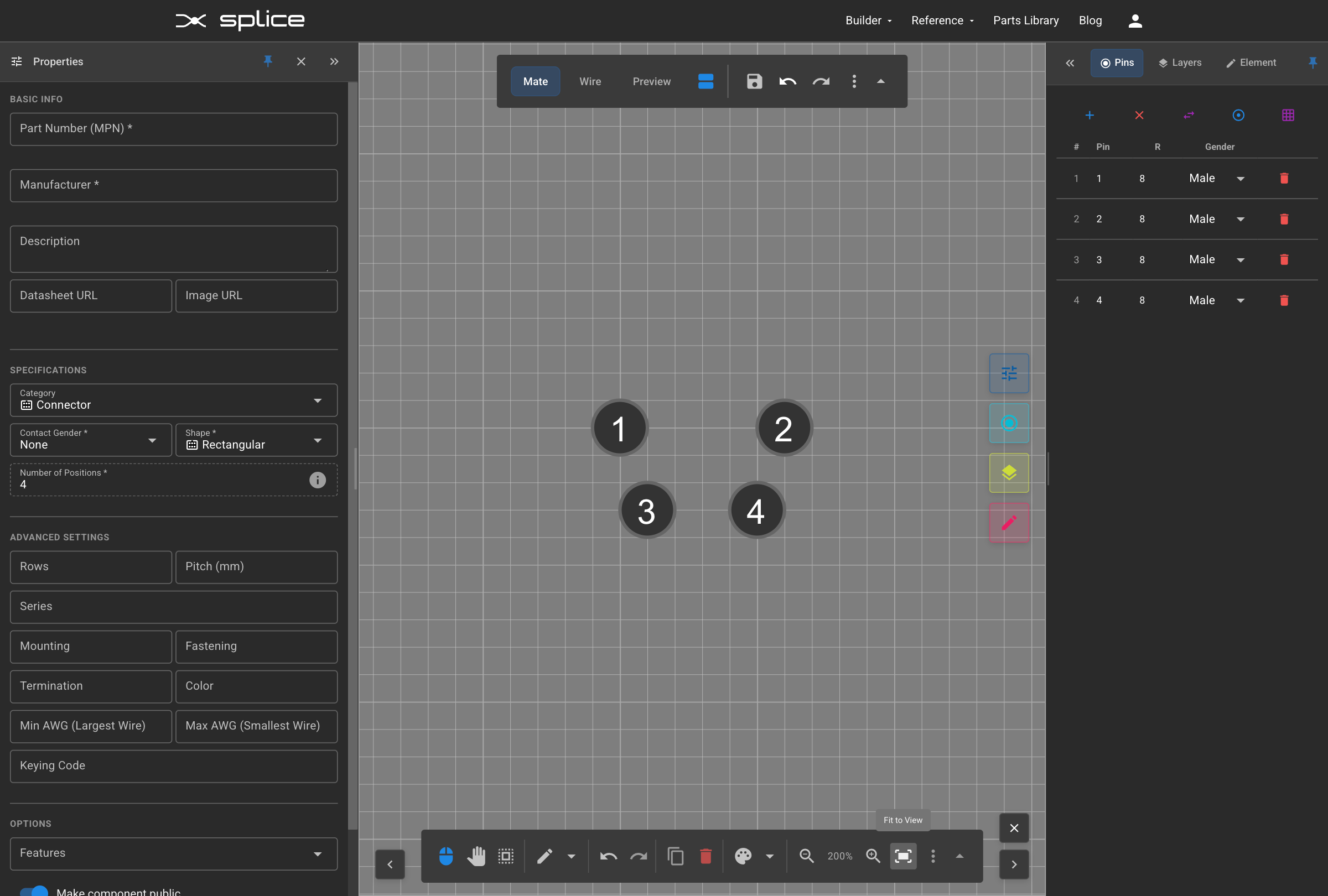
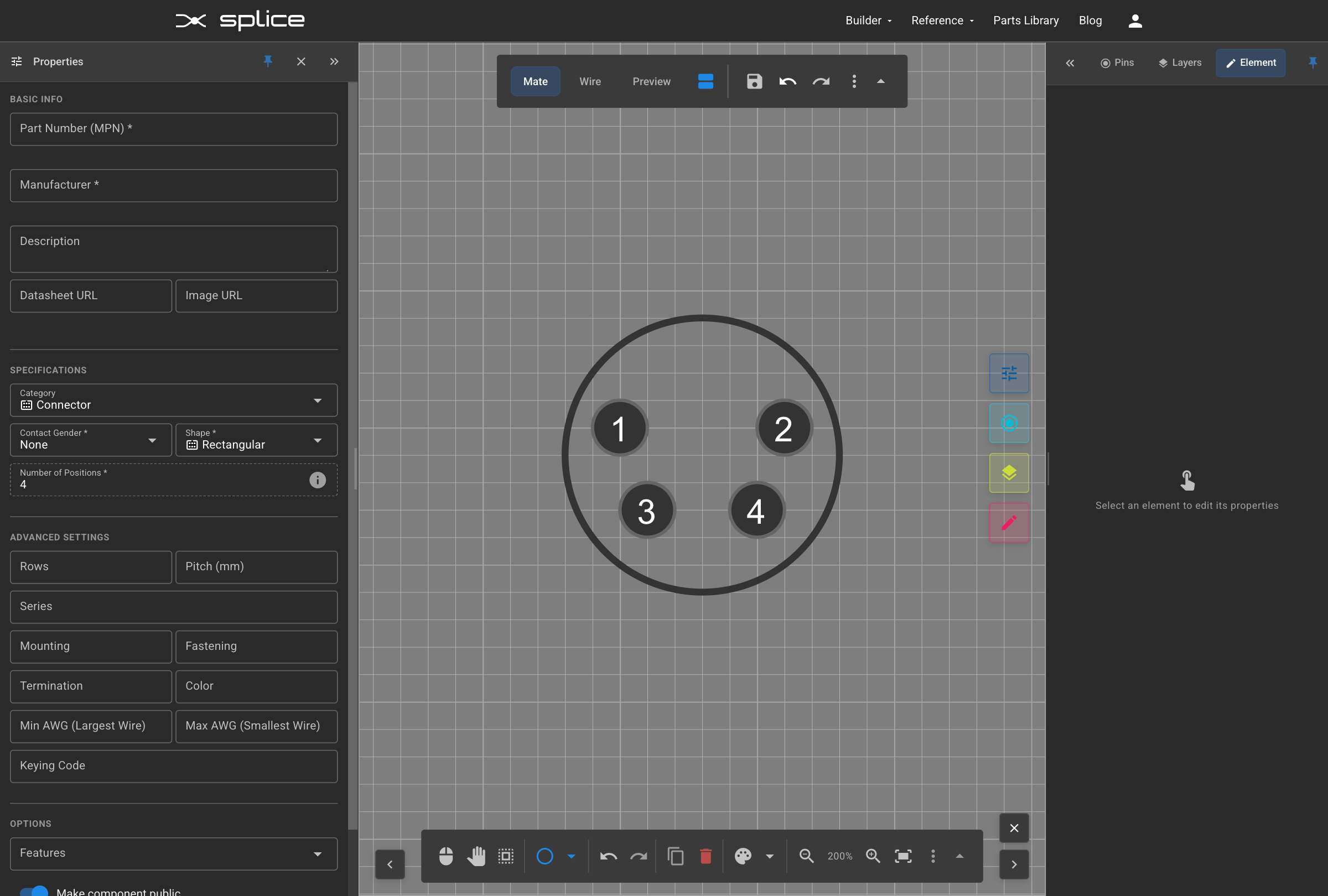
- Click the Create button at the top right to enter generic creation mode.
- Step 1: Select a category (Connector, Circuit Breaker, Fuse, etc.)
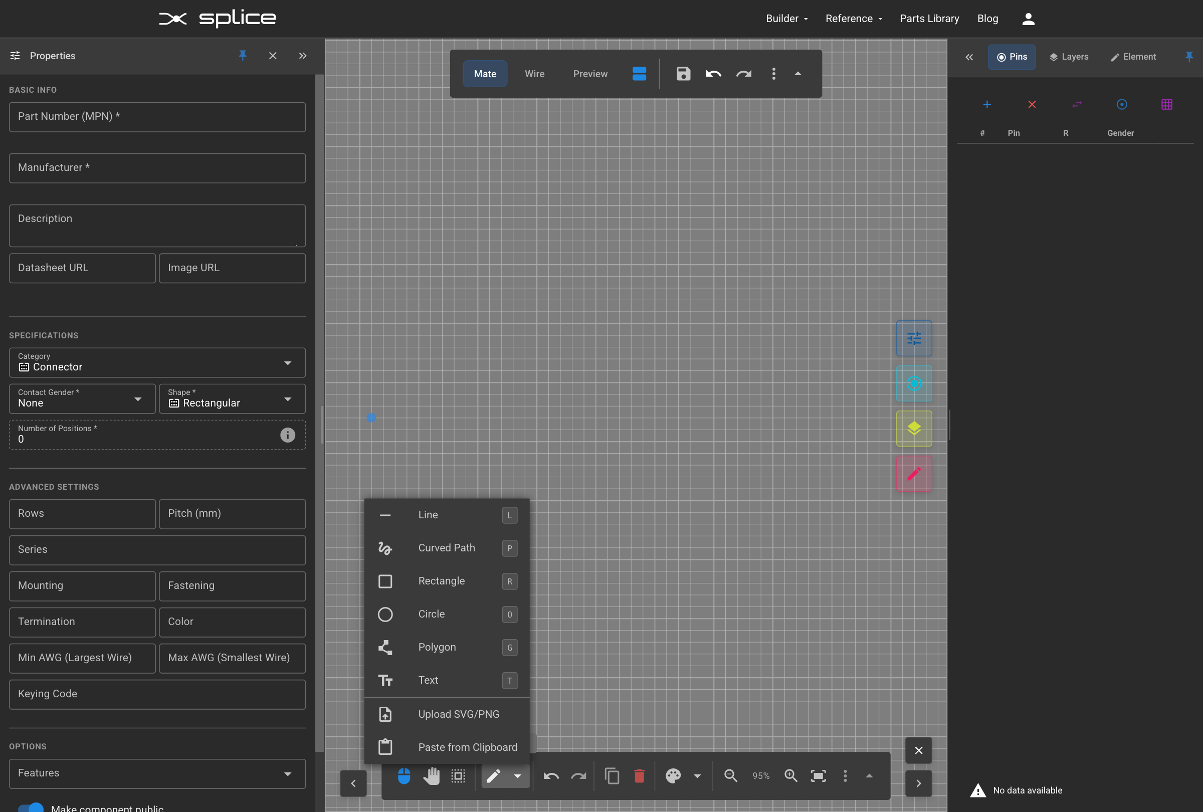
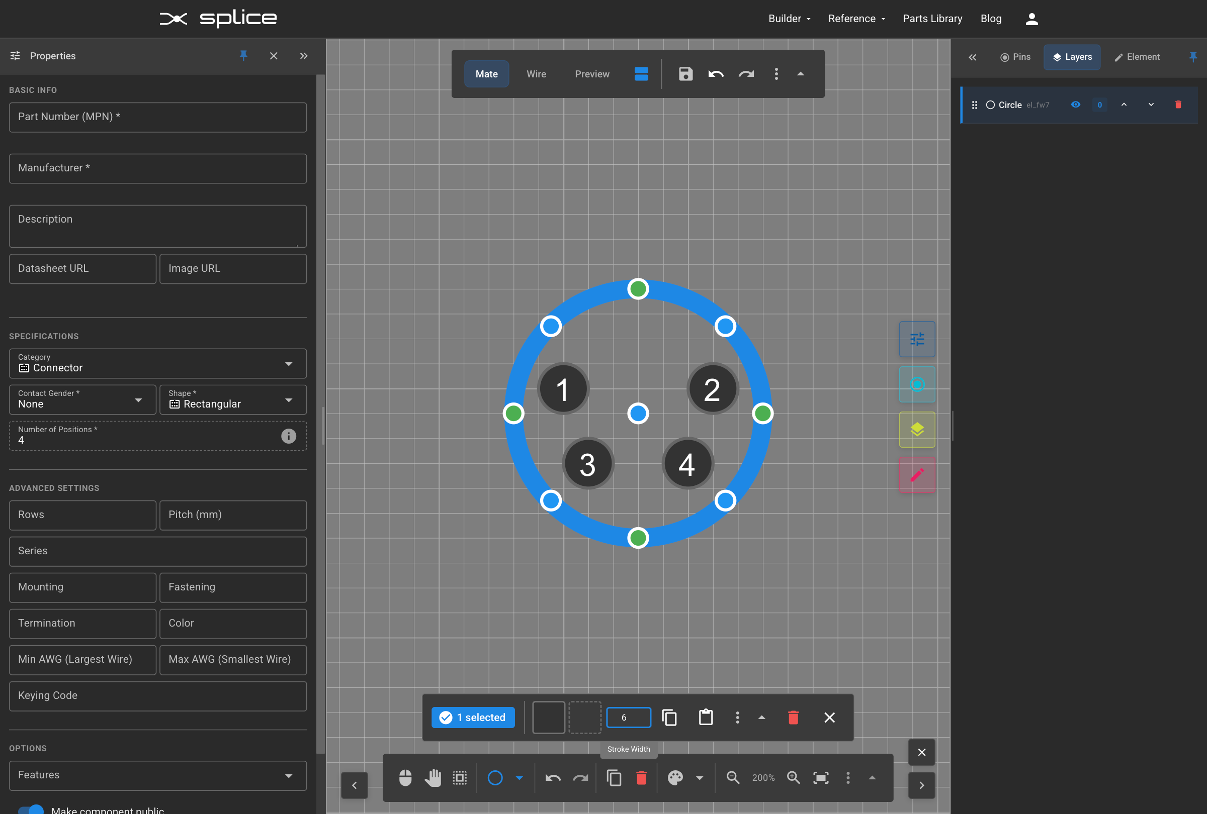
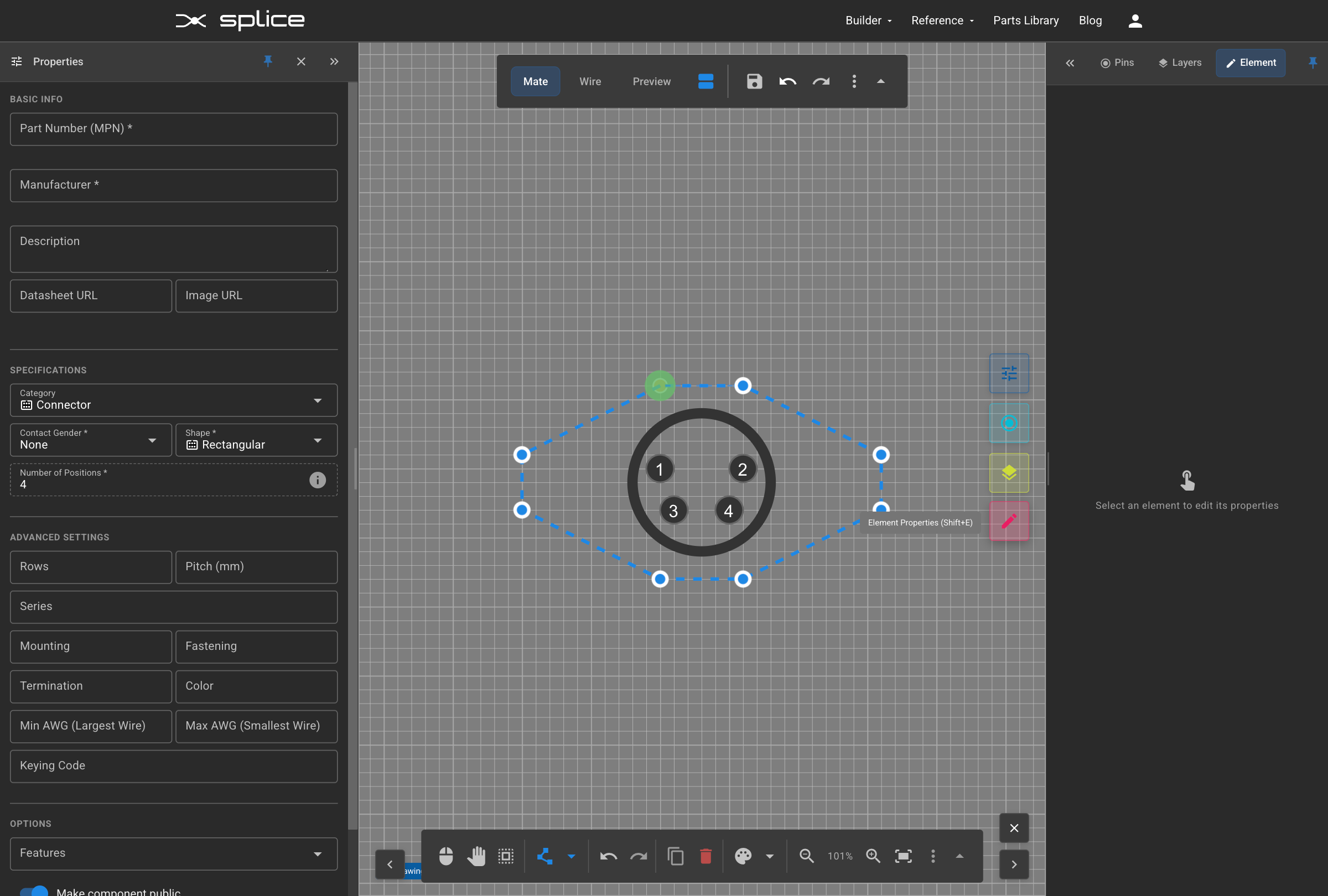
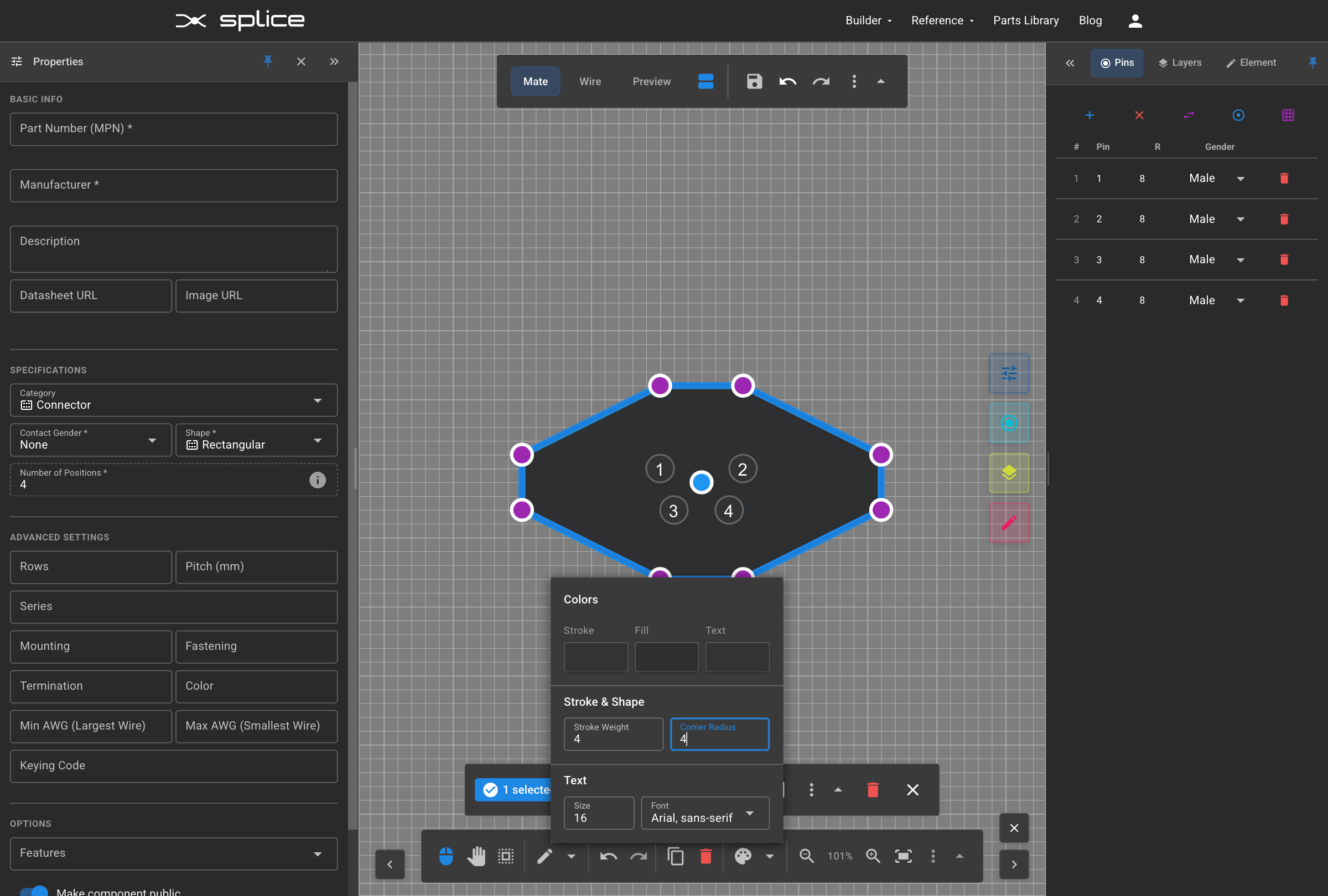
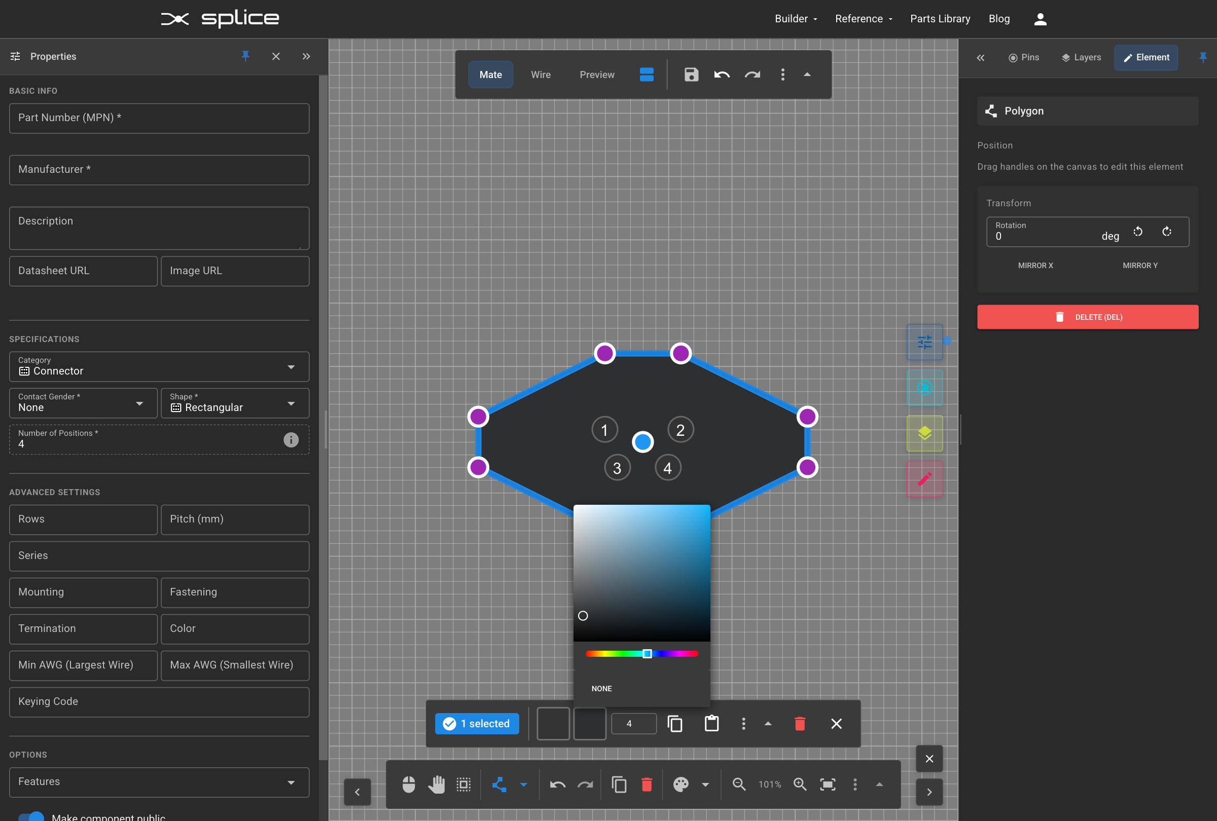
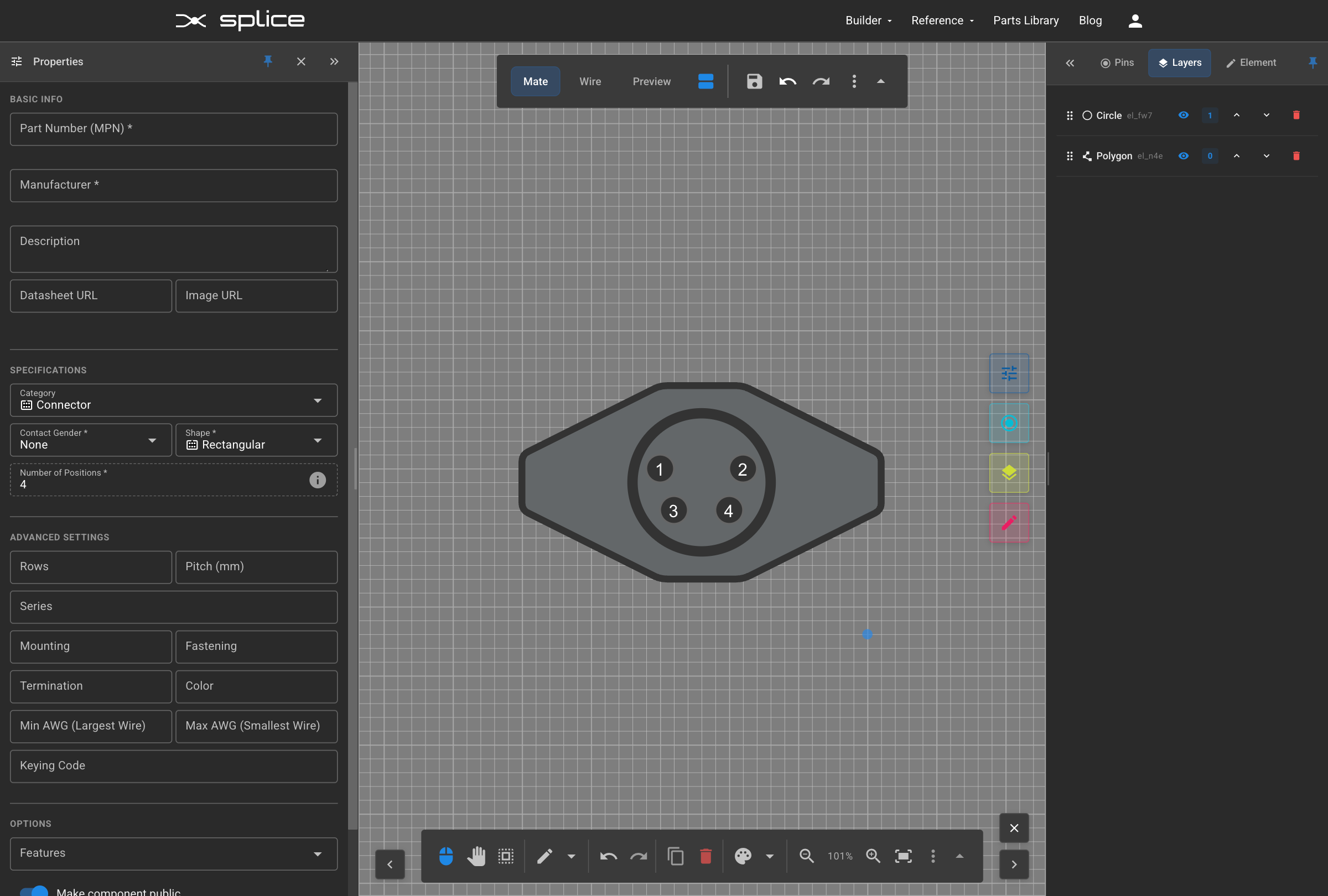
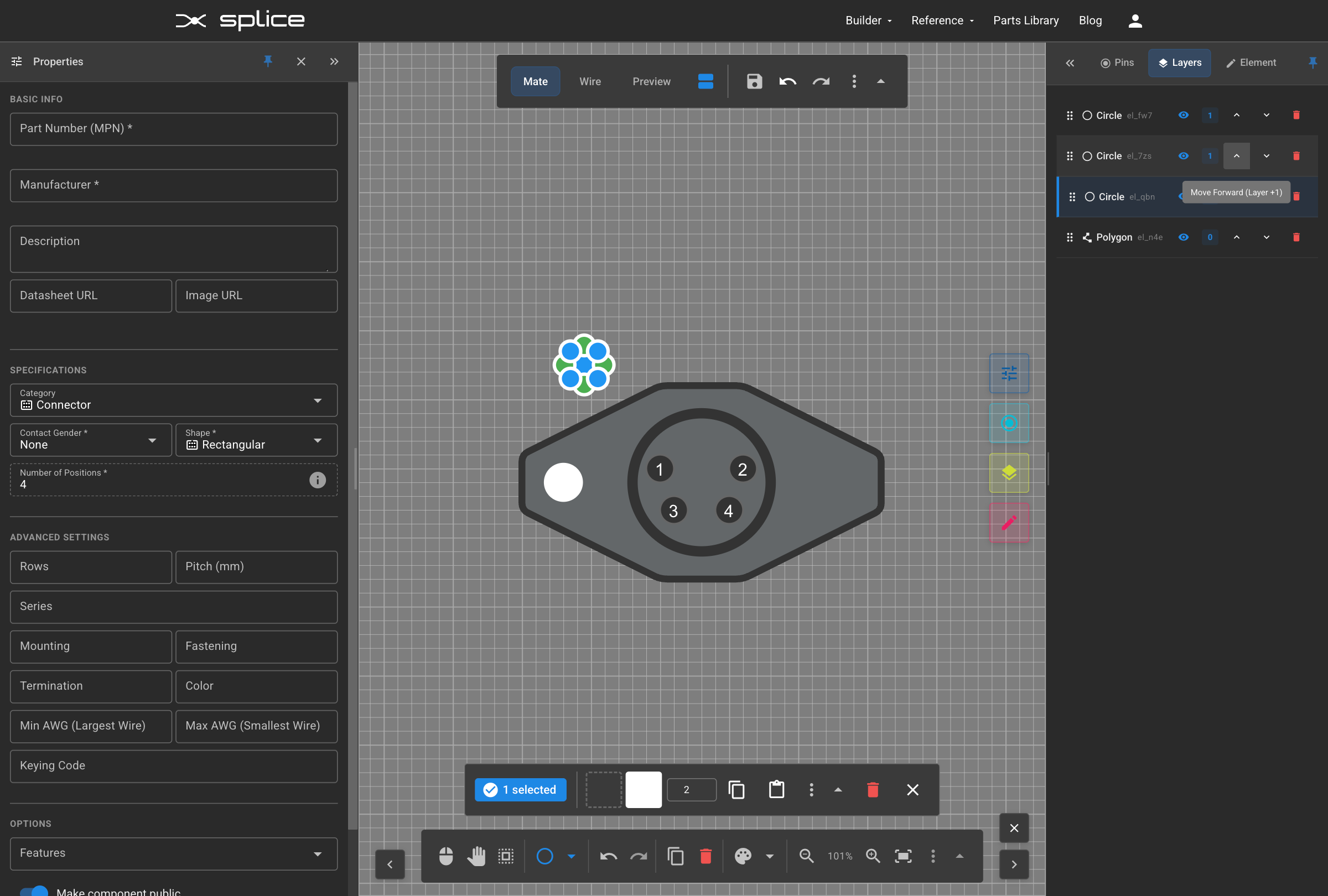
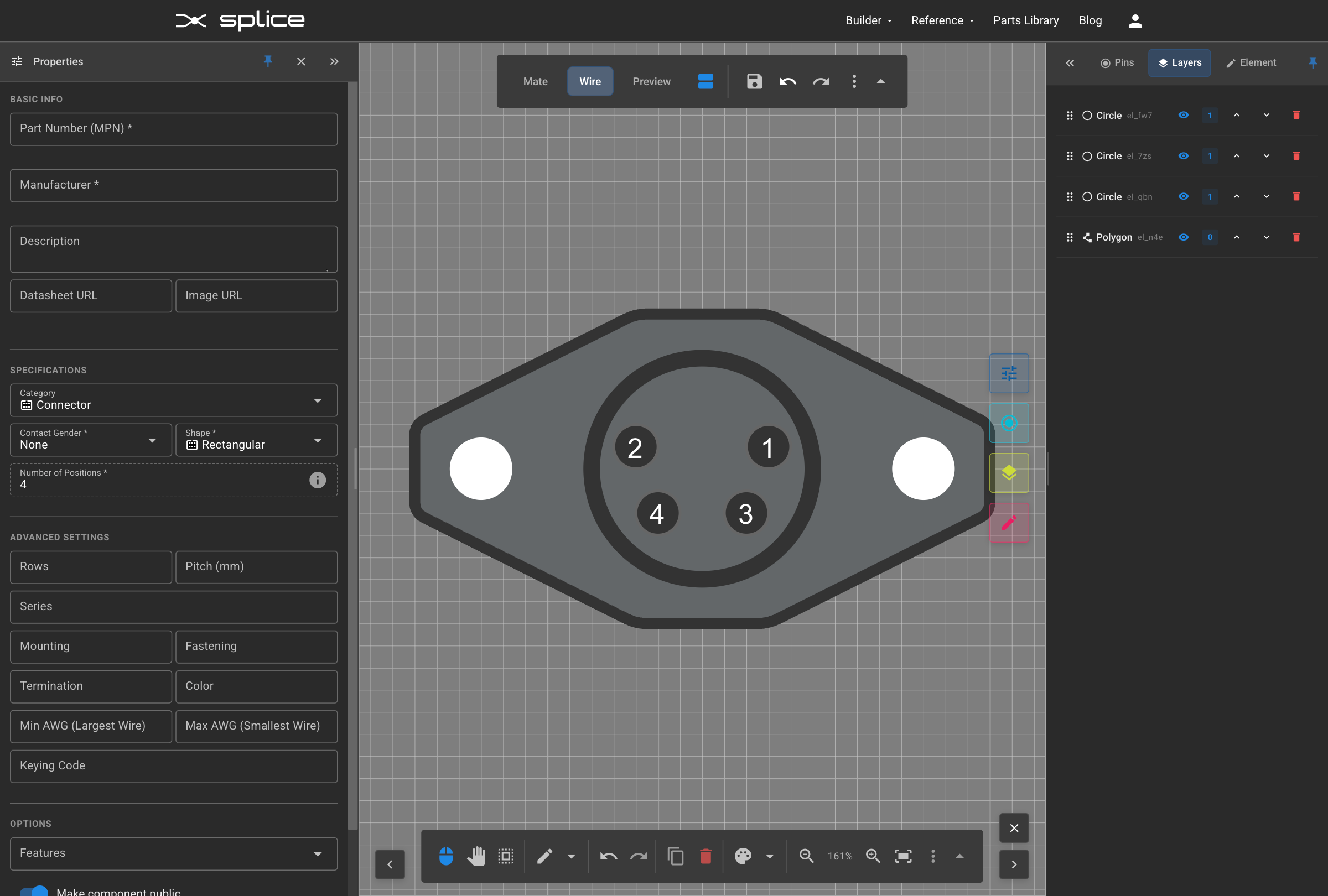
- Step 2: Choose a visual template from the grid, or upload custom SVG graphics
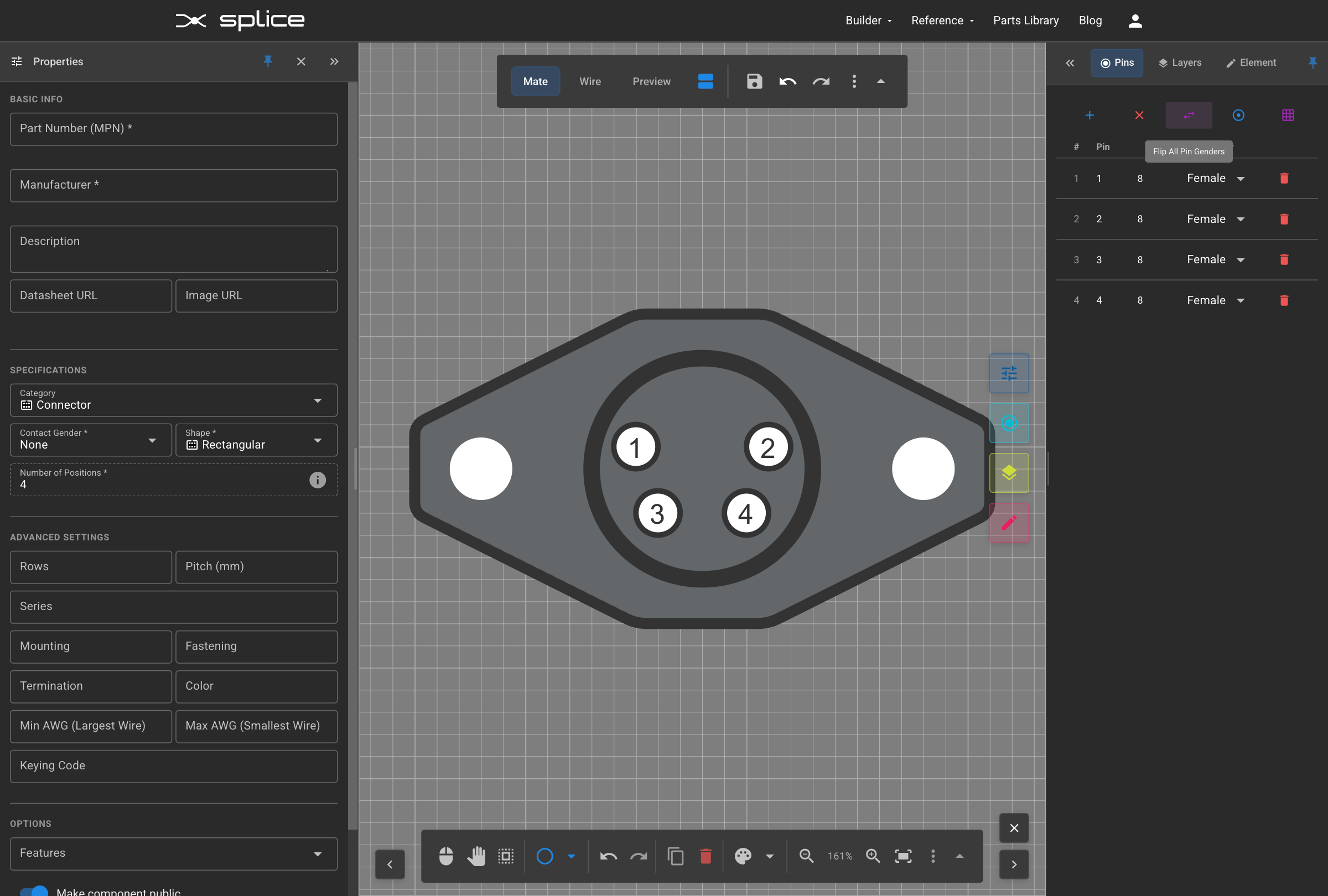
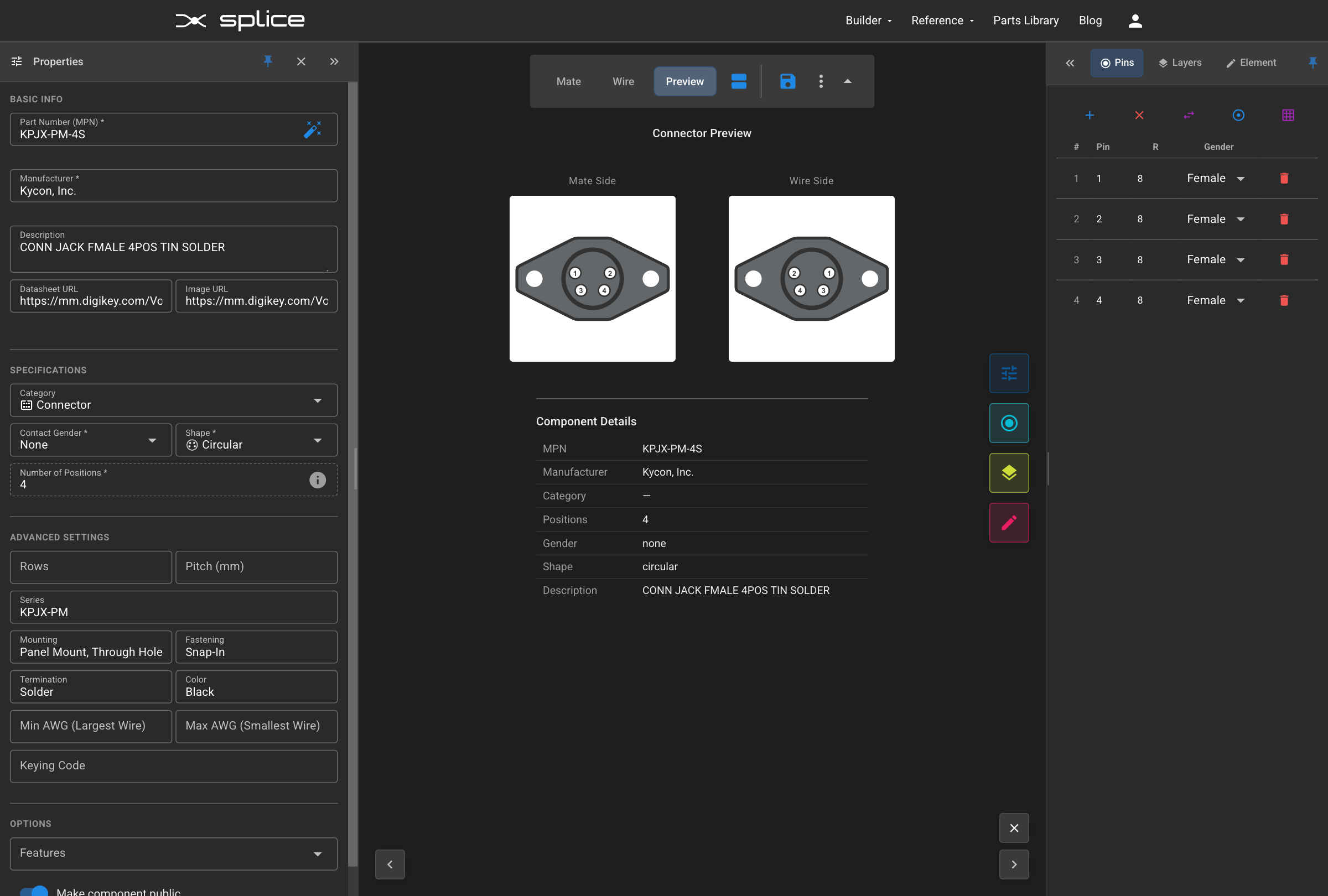
- Step 3: Fill in component details:
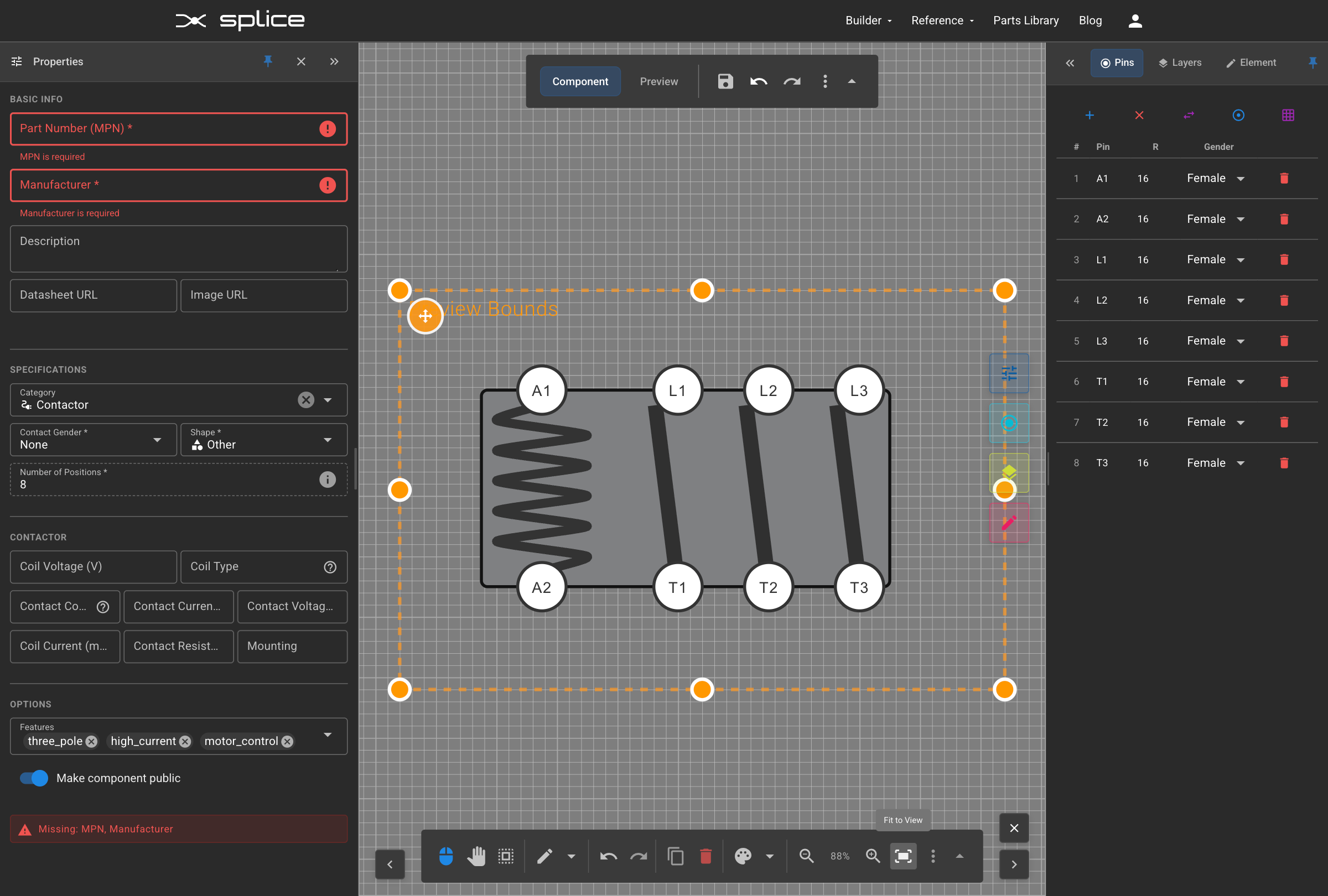
- MPN: Manufacturer Part Number (required)
- Manufacturer: Component manufacturer name
- Description: Brief description of the component
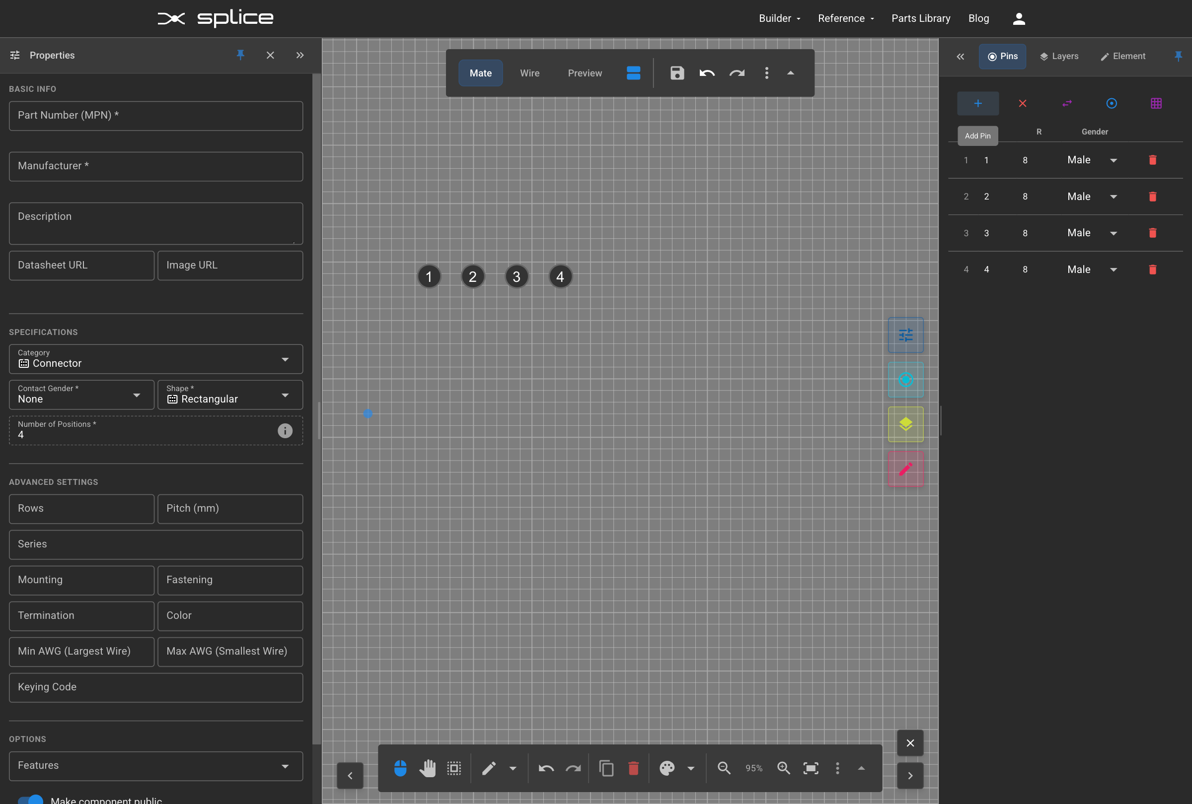
- Positions: Number of pins/contacts
- Datasheet URL: Link to manufacturer documentation
- Image URL: Link to product image
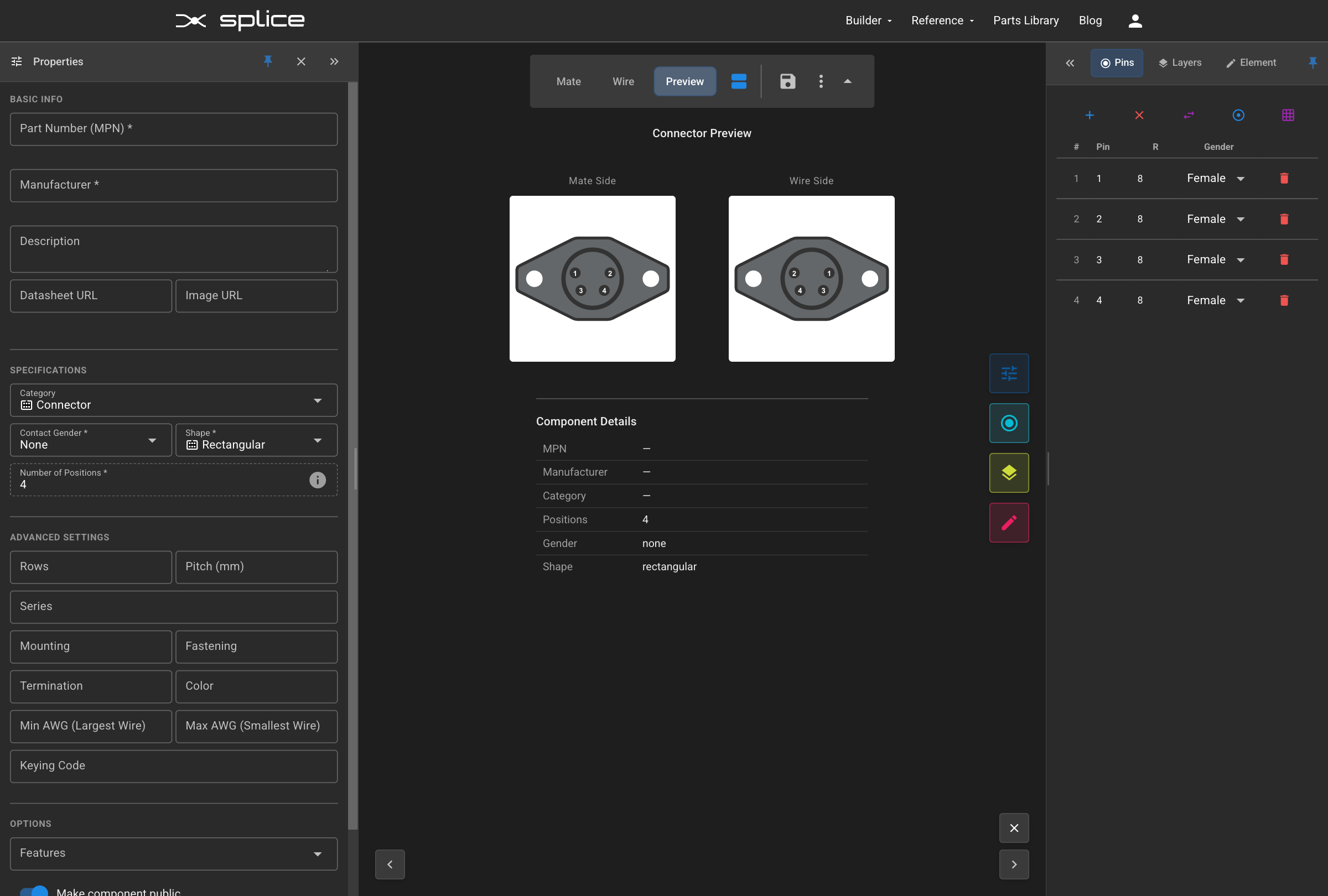
- Check "Make public" to share your component with other users.
- Click Create to add the generic component to your harness.
Positioning Components
Arrange Your Layout
Splice automatically routes wires and cable cores for optimal visibility. For clean layouts, position connector blocks, cable blocks, and wire bundle blocks in a logical pattern relative to each other.
Single Component Movement
- Drag components by clicking and dragging the header area.
- Use zoom controls for precision.
- Enable snap-to-grid for alignment.
Multi-Select Operations
- Box Select: Click and drag to select multiple items.
- Ctrl+Click: Add individual items to your selection.
- Group Move: Drag any selected item to move the group.
- Group Delete: Press Delete to remove all selected items.
Copy & Paste
- Ctrl+C: Copy selected components
- Ctrl+V: Paste to clone a component or cable
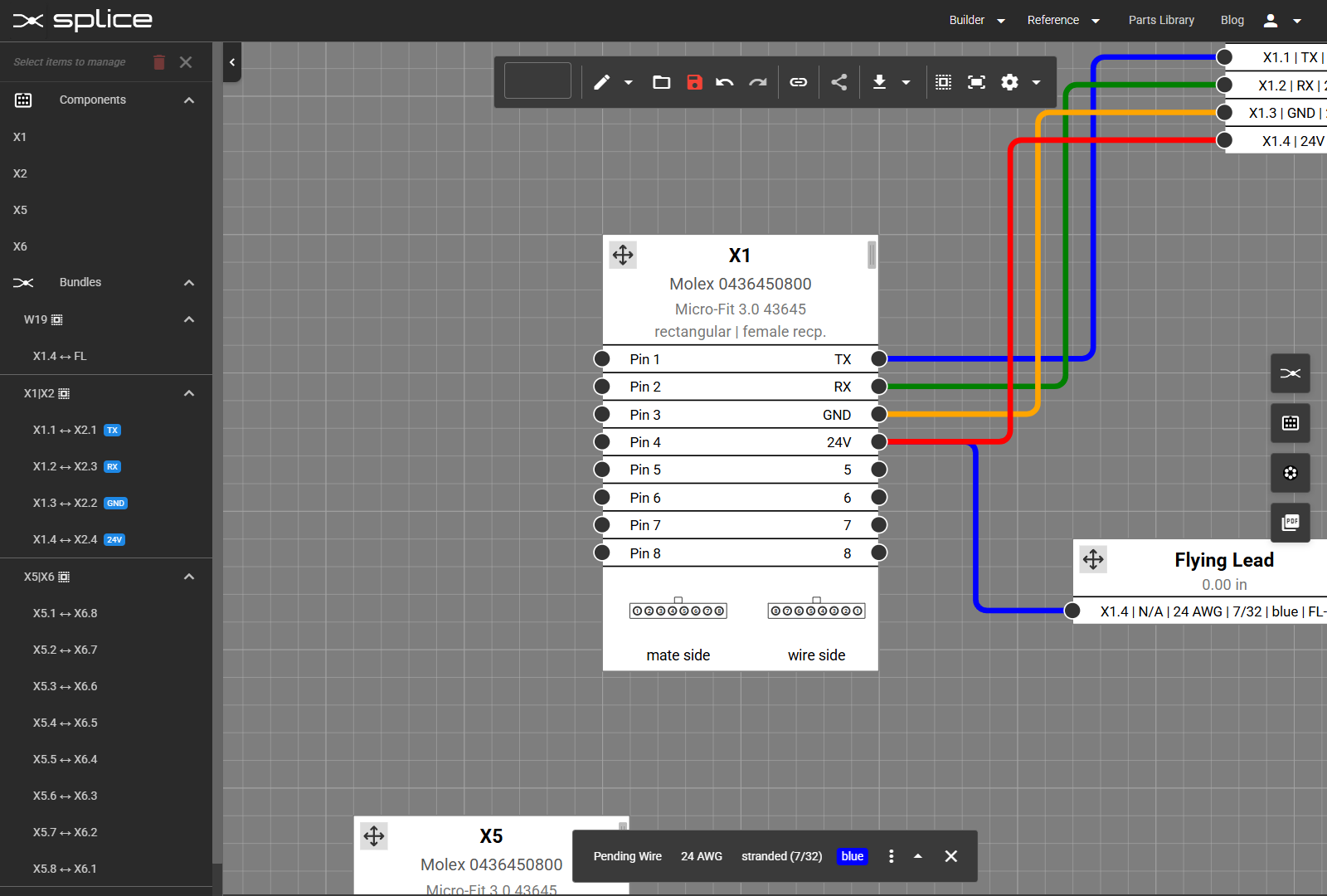
Component Blocks
Splice uses three visual block types—Component Blocks, Wire Bundle Blocks, and Cable Blocks—each with unique characteristics and controls.
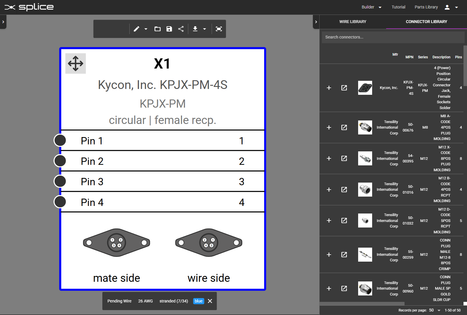
Component Block Header
- Designator: Auto-generated ID (X1, CB1, F1, SW1, etc.)
- Part Number: Manufacturer and MPN
- Type Description: Shape and gender designation, or category specific data
Designator Prefixes
CB1 Circuit BreakersF1 FusesS1 Push ButtonsSW1 SwitchesK1 RelaysKM1 ContactorsKT1 TimersPS1 Power SuppliesM1 MotorsFAN1 FansPCB1 PCBsR1 ResistorsC1 CapacitorsD1 DiodesL1 InductorsT1 TransformersINV1 InvertersBAT1 BatteriesPV1 Solar CellsSP1 SplicesX1 Connectors (default)C1 CablesPin Section
- Pin Numbers: Default numbering, customizable with pin mapping.
- Signal Names: Editable labels for each pin.
- Connection Circles: Visual connection points.

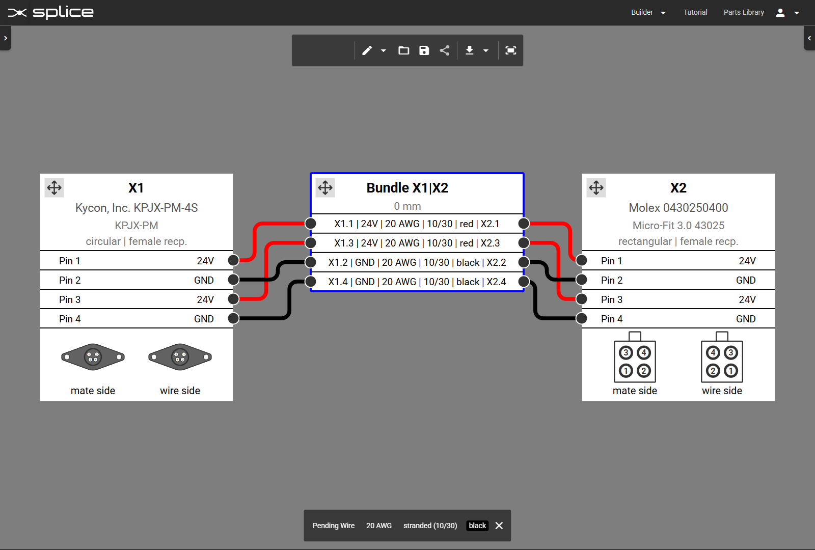
Wire Bundles
Bundle Header
- Bundle ID: Displays connected endpoints (e.g., Bundle X1|X2).
- Length: User-defined wire bundle length
Wire Information Format
- Format: "From | Signal | Gauge | Stranding | Color | To"
- Example: "X1.1 | TX | 22 AWG | 7/30 | blue | X2.1"
- Connection Points: Shows specific pin assignments

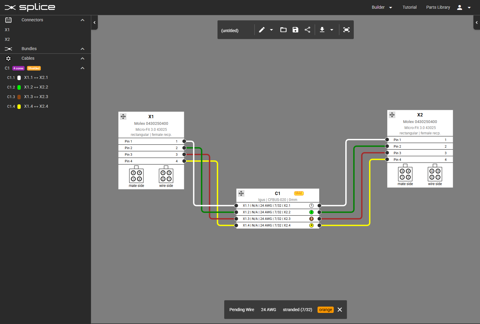
Cable Blocks
Cable Header
- Cable ID: Auto-numbered (C1, C2, etc.).
- Specifications: Manufacturer, part number, and length.
- Shield Indicator: Yellow "Shld." badge if shielded.
- Jacket Color: Visual indicator of cable jacket color.
Core Structure
- Core Numbers: Sequential conductor identification (1, 2, 3, 4...)
- Color Coding: Individual core colors for identification
- Core Numbers in Circles: Quick visual reference
- Shield Connection: Separate row for shield connection

Making Connections
Connect Pins with Wires
Use the Wire Library to select wires and create connections between component pins.
Basic Connection Process
- Click the Wire Library button on the right toolbar.
- Select a wire type from the library.
- Click the first pin to connect.
- Click the second pin to complete the connection.
- The wire will auto-route between the pins.
Managing Connections
- Click a connection to open the property editor at the bottom of the canvas.
- Edit wire properties such as color or gauge without breaking the connection.
Bulk Editing Wires
- Select a wire bundle in the left sidebar or Ctrl+Click multiple wires on the canvas.
- Edit all selected wire properties as a group in the property editor.
Wire Routing & Waypoints
Control Wire Paths
Wires and cable cores include a vertical jog between endpoints. This position is calculated automatically but can be adjusted manually for improved clarity.
Auto-Route Bundles or Cables
- Click the header of a wire bundle or cable block to reveal controls.
- Click Auto-Route to apply automatic routing.
- Click Fix Waypoints to lock the jog position.
Manually Adjust a Single Wire
- Select the wire by clicking on it.
- Drag along its path to create or move waypoints.
- Adjust each waypoint handle for precise routing.
Move All Wires on a Block Side
- Click the block header to reveal controls.
- Use the or buttons at left and right of the block to shift all wires on that side.
Signal Names
Label and Configure Connections
Assign signal names to improve documentation and clarity in manufacturing.
Editing Signal Names
- Click the header of a connector block to reveal controls.
- Click Edit to open the Edit Signals dialog.
- Enter descriptive names such as
PWR_12V,GND,CAN_H. - Signal names will appear in the BOM and exported documents.
Connection Management
Move or Swap Existing Connections
Moving a Connection
- Click the occupied pin to open the Connection Management dialog.
- Select the wire or cable core in the Move/Swap/Twist Connections list.
- Click the target pin to move the wire.
- If the target pin is occupied, choose Move Here to keep its existing connection.
Swapping Two Connections
- Click the occupied pin to open the Connection Management dialog.
- Select the wire or cable core in the Move/Swap/Twist Connections list.
- Click another occupied pin to swap with.
- Select Swap to complete the change.
Adding Cables
Add Multi-Core Cables
- Click the Cable Library button on the right toolbar.
- Search by cable type, gauge, or conductor count.
- Click to add the cable to your harness.
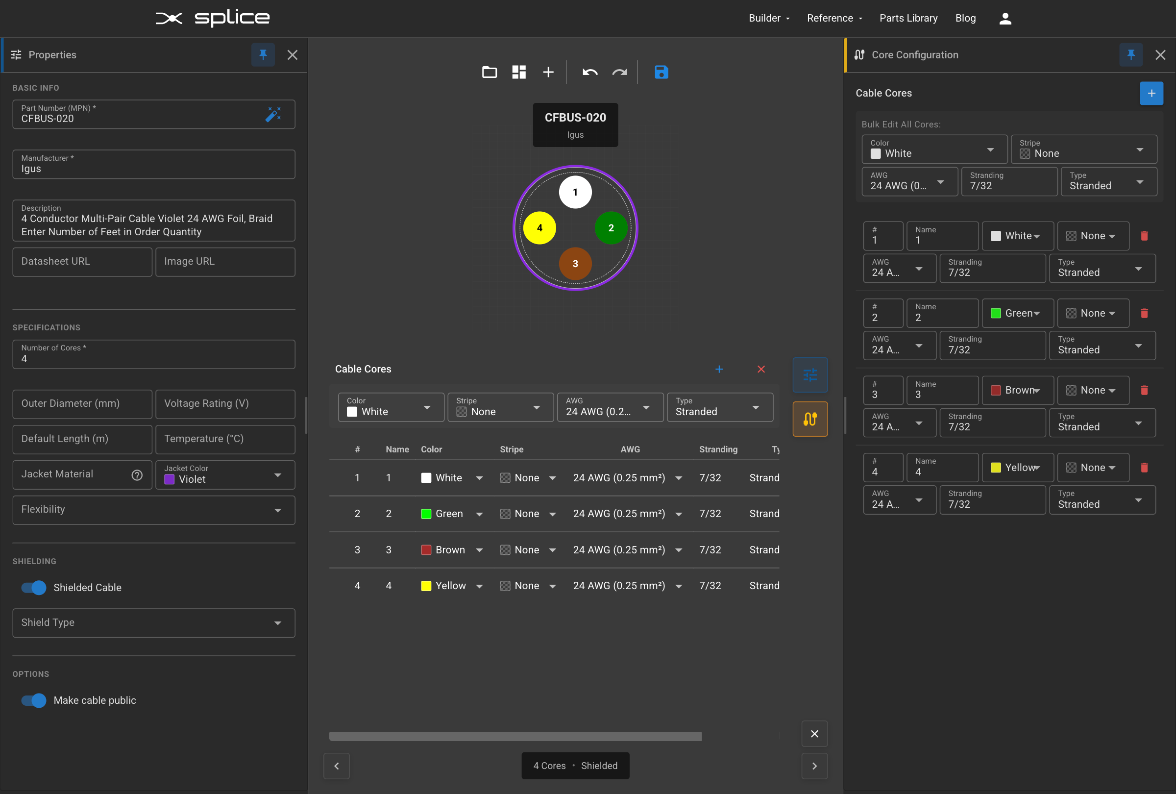
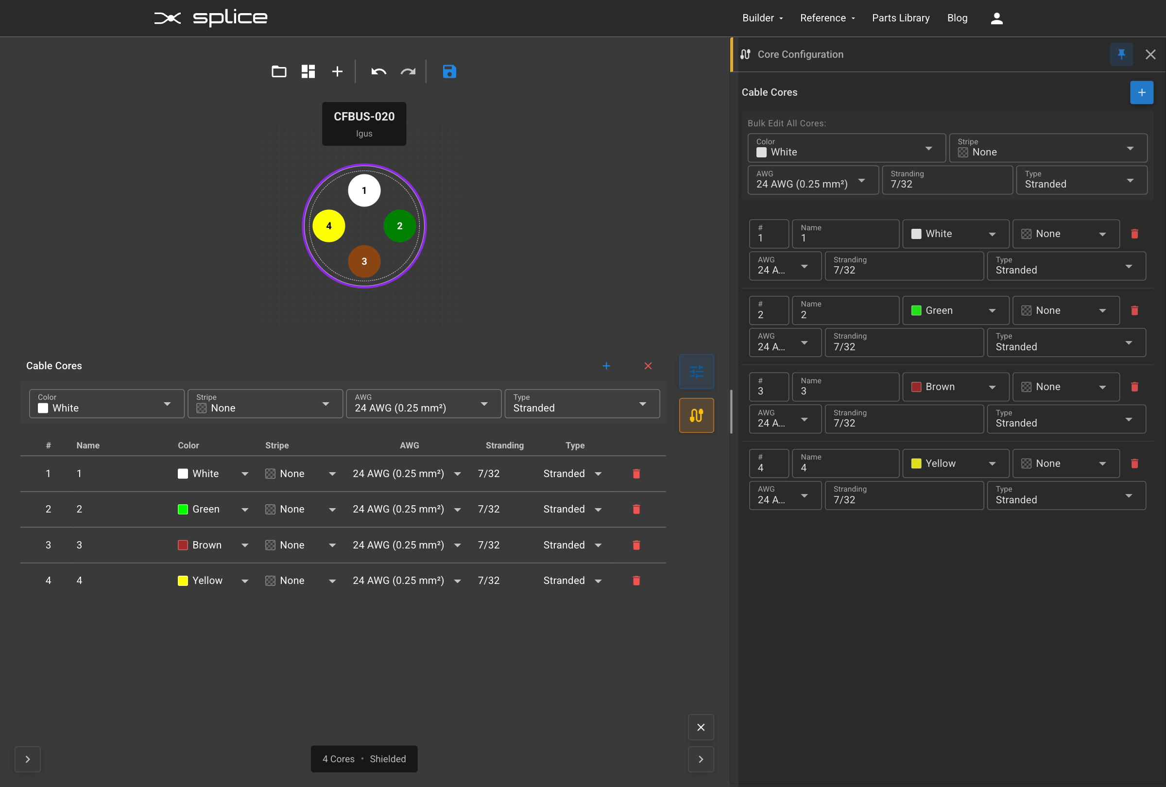
Creating Generic Cables
Build Custom Cables
When a specific cable isn't in the library, you can create a generic cable with custom conductor counts, gauges, colors, and specifications.
Creating a Generic Cable
- Click the Cable Library button on the right toolbar.
- Click the Create button at the top right to enter generic creation mode.
- Fill in basic properties:
- Part Number: Cable part number
- Manufacturer: Cable manufacturer
- Description: Cable description
- Configure cable specifications:
- Number of Cores: Total conductor count
- Shielded: Yes/No shield option
- Shield Type: Foil, Braid, or Spiral
- Jacket Color: Outer jacket color
- Cable Cores: Configure each individual core
- Bulk Edit: Set AWG, stranding, color, and stripe for all cores at once
- Individual Core Config: Customize designation, AWG, stranding, color, and stripe per core
- Live Preview: See cross-section diagram as you build
- Save as custom cable: Optional checkbox to save to your library for reuse
- Click Create to add the generic cable to your harness (and optionally to your library).
When to Use Generic Cables
- Custom multi-conductor cables not in the standard library
- Specialized industrial or military-spec cables
- Custom color coding requirements
- Prototype harnesses with unique cable specifications

Bundle Labels
Add Visual Labels to Connectors
Bundle labels help identify harness sections, add assembly instructions, or mark important locations on your design.
Adding Labels
- Click a connector on the canvas to show its toolbar.
- Click label icon in the toolbar.
- Click Add Label to create a new label.
- Enter the label text and customize the appearance.
Label Properties
- Label Text: The text displayed on the label tag.
- Background Color: The fill color of the label.
- Text Color: The color of the label text.
- Width: Label width in millimeters (for heat-shrink export).
Wire Association
- Labels can be associated with specific wire bundles.
- Associated labels appear in wire label exports.
- Use the dropdown to select which bundle a label belongs to.
Wire Label Export
- Export labels as a CSV file for label printing.
- Includes label text, dimensions, and wire associations.
- Compatible with Brady, Brother, and other label printers.
Bulk Operations
Use the Bulk Connect Tool
- Click Bulk Connect in the top toolbar.
- Select two components (or a component and a cable) to connect.
- Choose a connection pattern:
- Straight-Through: 1→1, 2→2, 3→3...
- Crossover: 1→N, 2→N-1, 3→N-2...
- Custom: Define your own pin mapping
- Set wire properties for all connections.
- Preview before applying.
Bulk Property Editor
Edit properties of multiple components, wires, or cables in a spreadsheet-like interface.
- Press E or click Bulk Editor in the floating panel menu.
- Components Tab: Edit instance IDs, descriptions, and renumber components sequentially.
- Wires Tab: Edit wire color, AWG, length, and toggle bundle visibility for multiple wires at once.
- Cables Tab: Edit cable properties and lengths in bulk.
- Changes are applied with undo/redo support.
Collapse/Expand Components
Simplify complex diagrams by hiding unused pins and cable cores.
- Right-click on the canvas background to access the context menu.
- Collapse All: Hides all empty/unused pins on connectors and cores on cables.
- Expand All: Shows all pins and cores, including unused ones.
- You can also collapse/expand individual connectors via their right-click menu.
Bundle Visibility Controls
Control the visibility of wire bundle blocks without affecting the wire paths themselves.
- Right-click on a bundle and select Minimize Bundle or Expand Bundle.
- Use Minimize All Bundles or Expand All Bundles from the canvas context menu.
- When minimized, wire paths remain visible and interactive—only the bundle block is hidden.
- Toggle Compact View on bundles to show a condensed version with less detail.
Export & Documentation
Create Manufacturing Documentation
PDF Multi-Page Export
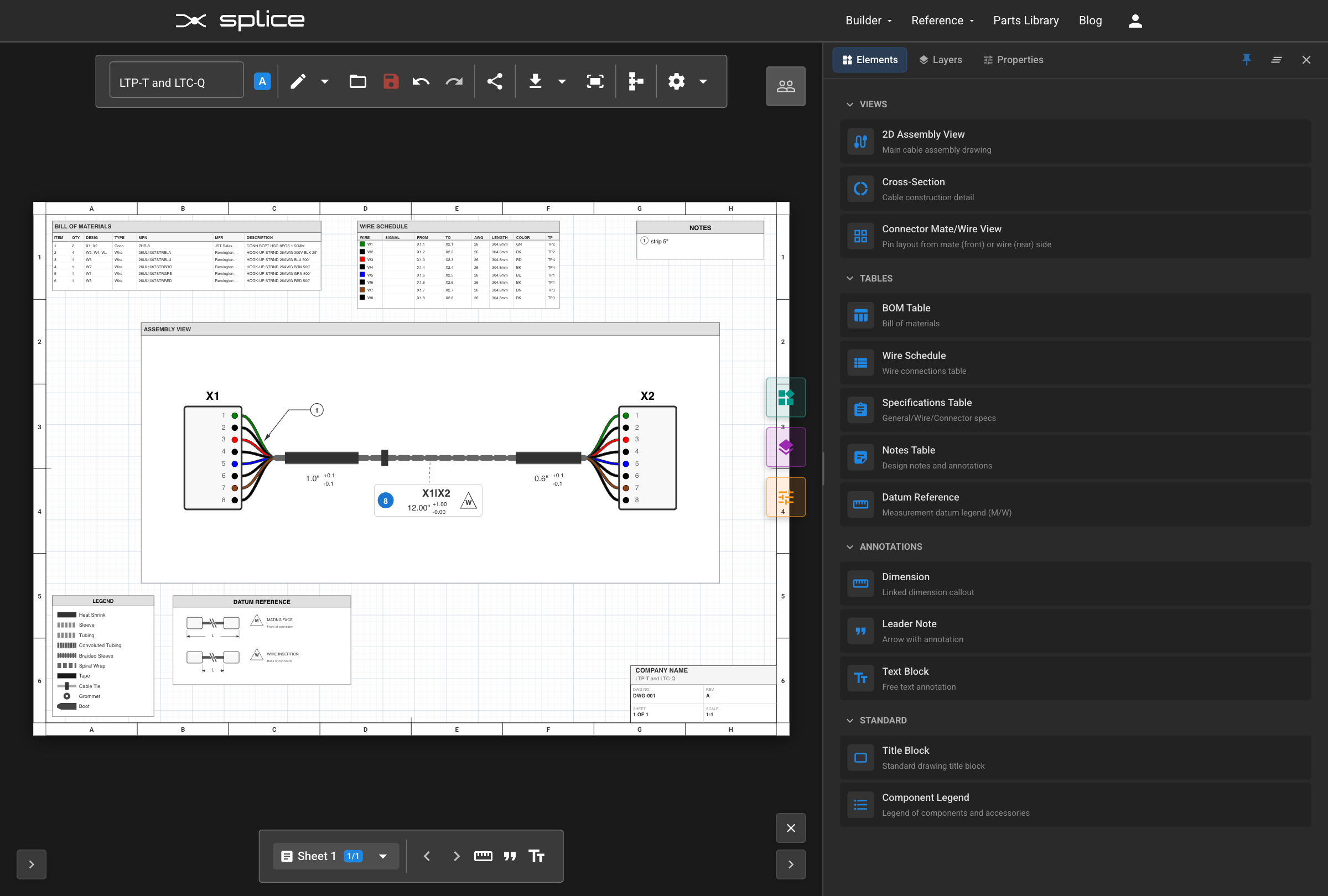
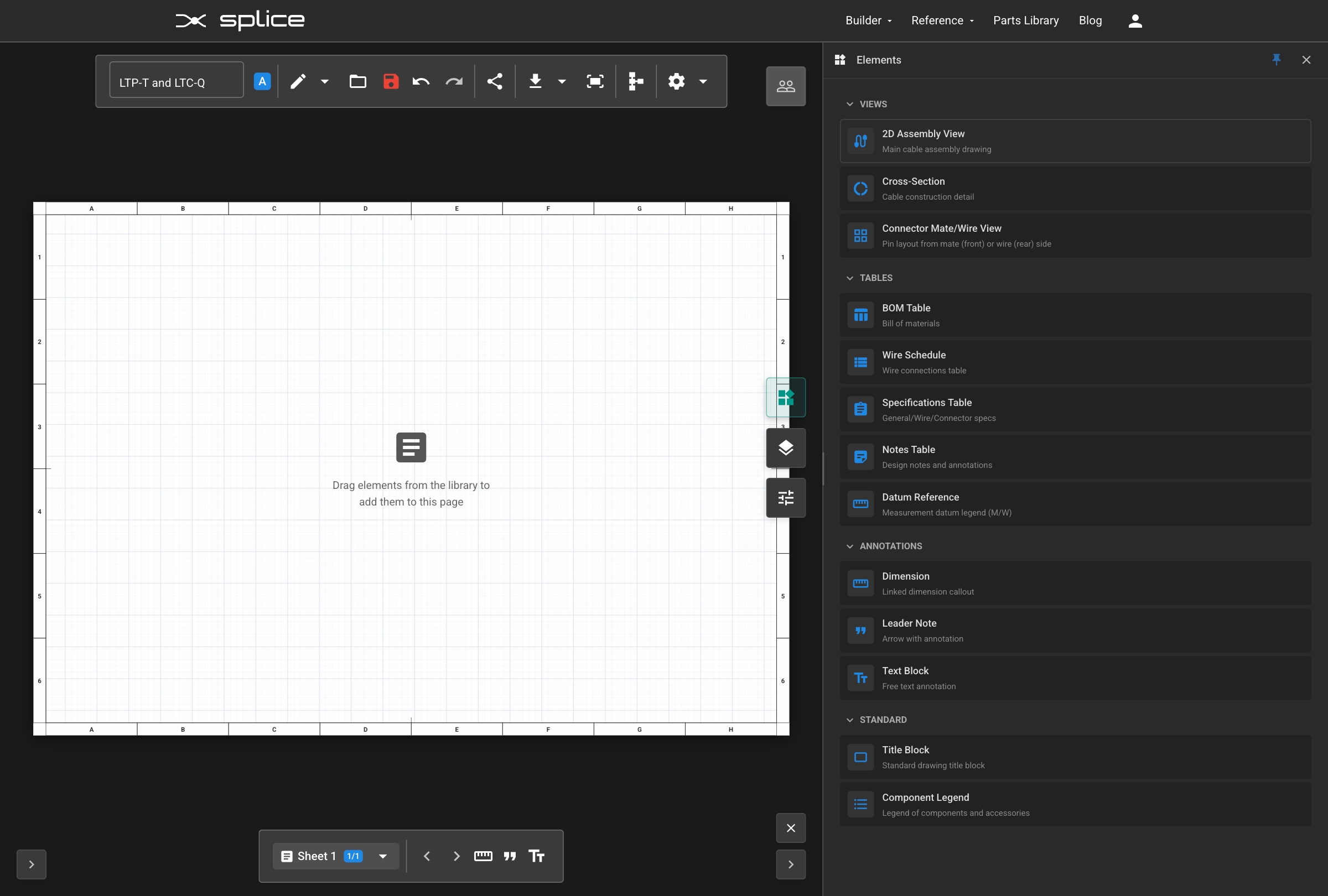
- Click the PDF Pages button on the right toolbar.
- Add multiple pages with custom sizes (A2, A3, A4, Letter, or custom dimensions).
- Position and scale page frames over your design.
- Export as multi-page engineering drawings with BOM, Connection Table, and Cut List.
BOM Placement Options
- Toggle "BOM on separate page" in the PDF Pages panel to control BOM placement.
- When enabled (default): BOM renders on dedicated page(s) after the diagram, followed by Connection Table and Cut List.
- When disabled: BOM overlays on each diagram page corner.
Connection Table Export
- Detailed wire-by-wire connection information grouped by bundle.
- Shows from/to pins, signal labels, wire color, AWG, and length.
- Included automatically in multi-page PDF exports.
- Available via Download & Upload > Connection Table.
Cut List Export
- Consolidated wire requirements with total length calculations.
- Groups wires by MPN and manufacturer.
- Shows length distribution (e.g., "3 x 200mm, 2 x 350mm").
- Export as CSV, Excel (XLSX), or PDF.
- Available via Download & Upload > Cut List.
Available Export Formats
- PDF: Engineering drawings with BOM, Connection Table, and Cut List.
- SVG: Scalable vector graphics for print or web.
- PNG: High-resolution raster images.
- WireViz YAML: For use with WireViz visualization tool.
- JSON: Machine-readable project data.
- Cut List: CSV, Excel, or PDF with wire requirements.
- Connection Table: PDF with wire-by-wire connection details.
Project Management
- Save: Save your harness design to the cloud.
- Load: Load existing designs from your account.
- Share: Create a public link to share your design.
- Revisions: Access previous versions of your design.